
Mobiumata (a concatenation of Möbius strip and cellular automata) is a small interactive art piece that allows folk to play god to 1,500 LED cells wrapped into a Möbius strip.

When Scott Logic needed something to act as a talking point for a conference booth, as a big fan of all things flashy, shiny and interactive, I jumped at the opportunity to create something engaging that was roughly themed around AI. This post covers the inspiration for the idea, aspects of the fabrication, highlights of the embedded Rust firmware and some unexpected learnings along the way.
Flashy things
In previous projects I’d had cause to play with “smart” LEDs (e.g. WS2812b) and knew I wanted to find a way to apply them here. Even if you’ve not come across the name before, if you’ve seen any kind of colour changing twinkly lights recently, you’ve most likely borne witness to their capabilities. There are two reasons I really like using them -
Ease of use
The first is how easy it is to control the “16M” colours they can produce. Previously, controlling the colour of an RGB LED involved carefully controlling the signal to each of the individual colour LEDs to vary the intensity of each channel. Not only did this require very precise timing, but controlling multiple LEDs quickly used up the available outputs on whatever you used to drive the LEDs.
In comparison “smart” LEDs bundle a controller into the LED package. The controller handles the precise timing required to perform the Pulse-Width-Modulation. You then control the controller by providing colour data as an RGB byte sequence using just a single pin. Which leads me nicely onto…
Simple elegance
The second is simple elegance of the protocol. To explain it, let’s quickly see how these LEDs are connected (ignoring power/ground connections) -
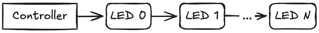
With the above topology there are a few different addressing strategies that could be used. We could give each LED an address and send packets of colour/address tuples but as we’re likely changing lots of colours at once, sending all those addresses is quite wasteful. How about instead we broadcast the colours for all addresses in one message?
This helps but we still have the problem of assigning addresses to each LED. What if we could somehow automatically assign an address based on the LEDs distance (in LEDs) from the controller?
It turns out this is not only easy, but it also greatly simplifies the design of the onboard controller. All it has to do is listen for the first colour, consume it (i.e. don’t propagate it) and propagate the remaining colours in the sequence.
I love the simplicity of this design and the ease with which you can trade refresh rate against the number of LEDs. Increasing the number of LEDs in any chain, increases the message size, which decreases the rate at which you can transmit messages.
Shiny things
In searching around online, I found that you can now buy matrices of these “smart” LEDs on flexible circuit boards. A recent theme park trip had also taught me that while animations look cool on flat surfaces, running the same animation on a curved surface, significantly enhances the effect. All without requiring any additional complexity, at least not on the software side -
Now all I needed was a curved surface to mount some of these LED panels on. From playing with the panel, I gained an appreciation of an appropriate bend radius (about 25mm), and also how hot they can get when you drive them hard. So this curved surface was also going to have to be made of metal. However, as my metal fabrication skills are somewhat lacking, I was limited to aluminium (soft enough to use wood working tools with) and some sort of simple shape, but what?
I’m not sure where the inspiration came from but the most organic looking shape that I could think of, that I also felt I had a hope of fabricating, was a Möbius strip -
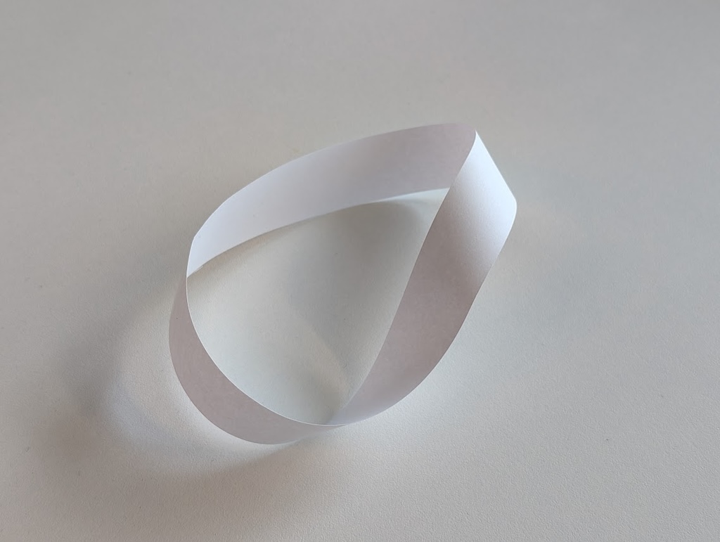
So we’ve got a bunch of LEDs in the shape of a Möbius strip, how do we make the whole thing interactive?
Interactive things
I think it probably reveals more about me than anything else, but Game of Life always comes to mind when I see a low resolution display. Unfortunately, the predominant axis of motion in GoL is diagonal. In this case we’re considering a display which is only 8 pixels tall. So whilst it would work, I think it would be an even more confusing and chaotic affair than normal.
When discussing my dilemma with my colleague Simon, he suggested that I look at Elementary Cellular Automaton. If you’re already familiar with GoL, then think of ECA as the 1-dimensional version of the 2-dimensional GoL. For everyone else, here’s a quick explainer (by Cormullion)-

In this animation you can see that the next generation of the automaton is created by applying the ruleset, in this case rule 30, to the current automaton contents. The rule specifies the output state of a cell based upon the cell’s state in the previous generation and its two adjacent cells. It fully describes all possible input states and their associated output state.
This was a great suggestion which maps very neatly onto a Möbius strip. Each generation of the ECA could be 8 pixels wide and generations themselves could progress infinitely around the strip.
The novelty of both ECA (and GoL) is that from these simple rules, can emerge seemingly complex behaviour. This is a bit of a spoiler but here are all the possible states of the mobiumata as they might appear on the unrolled mobiumata.
It also covers off the interactivity element, attendees could be invited to choose the rule and configure the wrapping behaviour (where the additional pixel comes from when deciding on the next generation state for a pixel at the top or bottom of the strip).
I had some chunky 2-position industrial switches lying around from a previous project so I could immediately picture one of those for each part of the rule. Throw in another 3-position variant to control the wrapping behaviour (zero-fill, wrap top-to-bottom/bottom-to-top or one-fill) and a push button to slow things down temporarily (to ease explanations to, or assist with discoverability for, attendees). This was pretty much building itself!
Looming deadlines
With the concept settled, reality hit and I was now left with the small matter of actually building it. Feeling more confident in my software abilities than my metalworking, I decided to start with the metalwork.
For the Möbius strip, I could reason that we’d need a piece of aluminium the height of the strip, and half the length of the combined widths of the strips. Plus a bit more to join the two ends together. I also knew that I would be bending at 60 degrees (to form a triangle) but I was less sure where I needed to put the bends and whether they should be interior or exterior bends.
I was about to embark on trying to model this in Fusion 360 to work out the measurements I needed, when it dawned on me that there was a much lower tech way (and quicker) way to achieve the same result: paper. If I scaled down the measurements, I could bend a piece of paper into the shape I wanted, mark the folds and then just scale those measurements back up again.
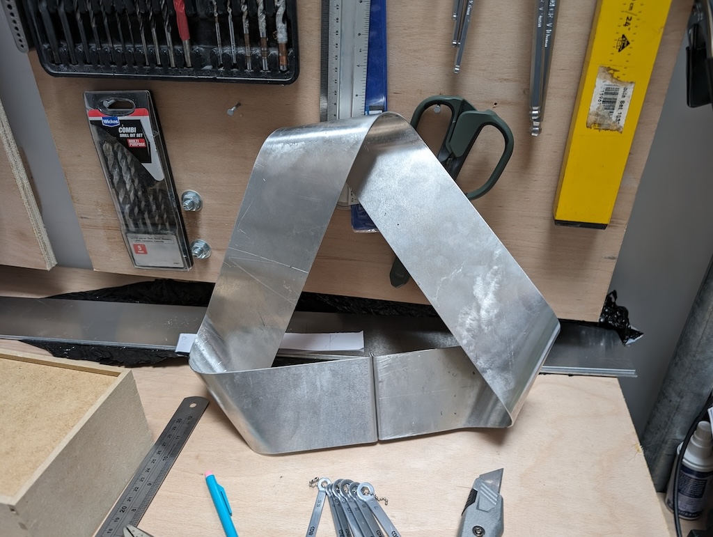
With a pattern to follow, despite making the bending a little more physical than it perhaps needed to be, I pretty much followed the techniques demonstrated in this tutorial video for bending right angles and curves.

It took a little while but I was very happy with the result. It almost felt a shame to cover it up with LEDs!
To allow the mobiumata to stand on a surface, I needed some kind of base. I considered making one but I’ve always found it’s much easier to customise something than it is to build it from scratch, especially when it’s not the main focus of a build.
There are definite parallels to software development somewhere in there…
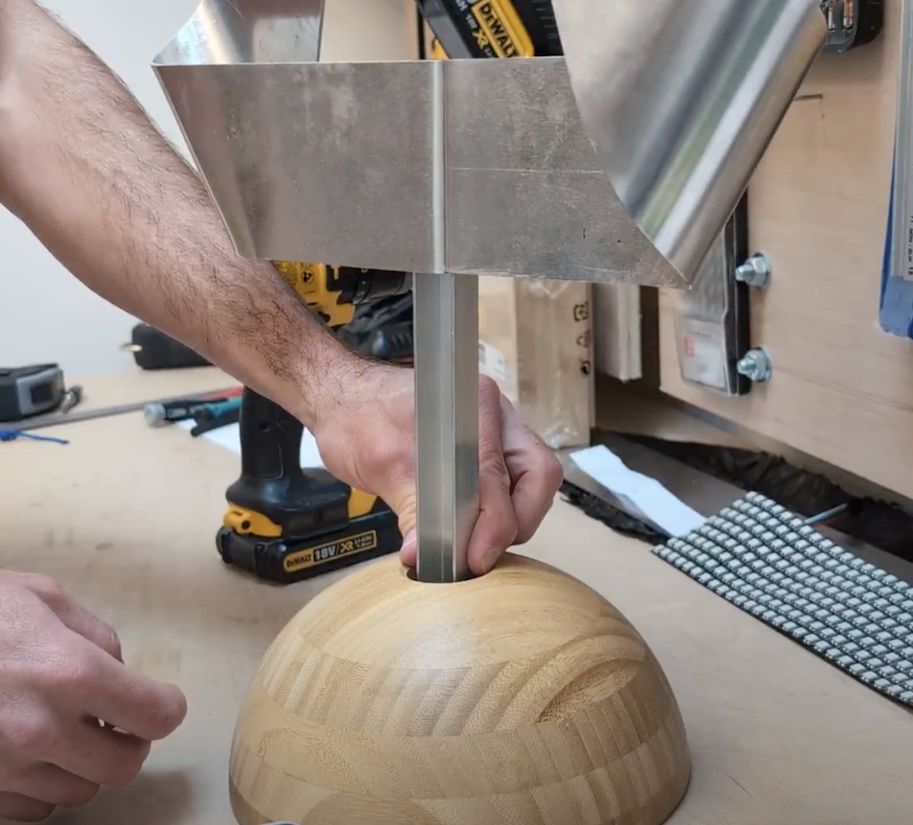
Anyhow, after hunting around the IKEA website I found a BLANDA MATT (bamboo serving bowl) that I figured upended, was about the right size and shape for a base. I attached a leftover piece of aluminium angle to the Möbius strip to act as a leg and drilled a hole for it in the base of the bowl. Subsequently and not shown below, I also ordered a short piece of aluminium tube sized to the hole, to allow the cables to be hidden in the leg.
For the controller, I found a somewhat matching TAVELÅN (bamboo bathroom tray) that again I figured upended, was about the right size and shape for a control box. This time I used my CNC machine to cut out the holes for the switches -
A massive LED strip
With the hardware somewhat in place, or at least the concept proven, it was time to turn to the software side. Whilst I’ve previously blogged about my first steps making a Vim clutch with embedded Rust, if you’re not familiar with the basic concepts and terminology (PAC, HAL, BSP), I’d highly recommend this video which does a much better job of explaining them.
Since writing my last post, the Rust ecosystem has somewhat embraced the use of async. This can greatly simplify application code by removing the need to explicitly maintain state machines and poll routines. For example, here’s the guts of the code from that post -
let mut switch_state = switch_pin.is_low().unwrap();

loop {
    usb_dev.poll(&mut [&mut usb_hid]);

    let previous_switch_state = switch_state;
    switch_state = switch_pin.is_low().unwrap();

    match (previous_switch_state, switch_state) {
        (true, false) => {
            info!("normal mode!");
            led_pin.set_low().unwrap();

            send_key_press(&usb_hid, &mut delay, KEY_ESC);
        }
        (false, true) => {
            info!("insert mode!");
            led_pin.set_high().unwrap();

            send_key_press(&usb_hid, &mut delay, KEY_I);
        }
        _ => {}
    }
}
And here is the same thing implemented using Embassy (an async runtime for embedded devices) -
loop {
    switch_pin.wait_for_high().await;
    info!("normal mode!");
    led_pin.set_low();
    send_key_press(&mut usb_hid, KEY_ESC).await;

    switch_pin.wait_for_low().await;
    info!("insert mode!");
    led_pin.set_high();
    send_key_press(&mut usb_hid, KEY_I).await;
}
Notice we’re no longer polling the USB device and there’s no explicit management of the switch state (also delay is now effectively global). In this extremely simplistic example, there’s not a huge difference in complexity but you don’t have to increase the complexity much for async to really shine.
A prime example of this is my original motivation for using Embassy. I wanted to have the mobiumata controllable remotely, necessitating something like WiFi. In the non-async world, there isn’t currently a driver available for the WiFi chip on the Raspberry Pi Pico W, whereas Embassy has had a functional driver for the last year or so.
With Embassy chosen, the bulk of the code required to show something on the display came from mashing together the pio_ws2812 example to control the LEDs with the wifi_ap_tcp_server example for running a WiFi Acccess Point and listening for TCP packets on the network. With these in place, from my laptop I could change the colour of the whole display or run a random pattern on it.
As a next step, I wanted to move towards a more functional display which could show something more interesting. So I decided to implement DrawTarget from embedded_graphics, a library for drawing 2D primitives optimised for embedded devices. The tricky bit here was mapping an X/Y “screen” co-ordinate onto the appropriate LED index (noting that the LEDs are physically connected in a zig-zag pattern) -
pub fn get_index(x: usize, y: usize) -> usize {
    if y % 2 == 1 {
        x + WIDTH * y
    } else {
        (WIDTH - 1 - x) + WIDTH * y
    }
}
Earlier, I covered the positives of async in Rust. Unfortunately, at this point I hit upon one of the negatives: the ecosystem is still quite fractured (see also What Color is Your Function?). Instead of being able to write out the data as part of the implementation of DrawTarget::draw_iter, I had to add a separate async function called flush so that I could .await the result -
pub async fn flush(&mut self) {
    self.ws2812.write(self.data[0..NUM_LEDS_PER_PIN].iter().copied()).await;
}
Finally the display was starting to look like… well… a display! Click through for a video version -

With the display in check, it was time to move on to the automata code itself. I was about to dig out the Wikipedia page and engage in some cathartic algorithmic work, when I realised this was a prime opportunity to unleash GitHub Copilot. With a bit of steering, it dutifully kicked out a perfectly serviceable implementation. The crux of which was -
pub fn next(&self, state: &[bool], next_state: &mut [bool]) {
    assert_eq!(state.len(), next_state.len());

    let len = state.len();

    for i in 0..len {
        let left = self.wrap.left(state, i);
        let center = state[i];
        let right = self.wrap.right(state, i);

        let index = (left as u8) << 2 | (center as u8) << 1 | right as u8;
        next_state[i] = (self.rule.0 >> index) & 1 == 1;
    }
}
For the controls, I just needed to expose the state from above i.e. the rule itself (a newtype wrapping an 8-bit unsigned integer) and the wrapping behaviour (an enum with values Wrap, Zero and One). A sprinkling of embassy-sync::Signal structs to handle marshalling the value between the network task and the main loop, and we end up with the final main loop of the display -
loop {
    for y_update in 0..HEIGHT {
        if let Some(new_state) = signal.try_take() {
            state = new_state;
            info!("New state: {:?}", state);
        }

        let automaton = ElementaryCellularAutomaton::new(state.wrap, state.rule);
        automaton.next_row(universe, y_update);

        let pixels = universe.iter().enumerate().flat_map(|(y, row)| {
            row.iter().enumerate().map(move |(x, cell)| {
                Pixel(
                    Point::new(y as i32, x as i32),
                    hsv(if *cell { 170 } else { 15 }, 255, 255),
                )
            })
        });

        display.draw_iter(pixels).unwrap();
        display.flush().await;

        ticker.next(state.step).await;
    }
}
The code for the controller itself is far simpler than the above. It just reads the state of the various switches and if any of them change, broadcasts the new state over the network.
Close calls
During the build there were a few unexpected twists and turns. The first one probably doesn’t need much in the way of explanation -
I ended up filling the resulting hole with some wood-filler and relied on folk being too busy playing with it to notice. And I was plesently surprised when this turned out to be the case.
Another consequence of this mishap was the odd looking engraved text. As I’d just destroyed my only engraving bit and didn’t have time to wait for another, I decided to run the engraving toolpath with a bull nose end mill. I thought it looked awful but I was again pleasently surprised when folk didn’t notice, assumed it was a conscious design decision or were too nice to say anything!
Doubling the refresh rate
A more fundamental problem cropped up when I was testing the combined LED sections, the refresh rate was just too slow to drive the animation at a speed that felt compelling.
To maintain the look of the piece, I’d assumed that I could only inject the data signal at the end of the strip where it would align with the base (so that the wires could be hidden inside). However, as I started to assemble the piece I realised that because it was a Möbius strip, the join between the third and fourth sections would also align perfectly with the base! And, as I covered earlier, if I split the sections here and injected a second data stream into the second half, I could double the effective refresh rate.
I was confident I could get the software side to work, but by this point I’d manhandled the sections a lot trying to get them all into place, before pulling them off to bifurcate them, then reattatching them. This made me a lot less confident things were mechanically/electrically holding up. Nevertheless, I made the requisite changes to the firmware. I modified Display such that it used two instances of Ws2812, running each on separate state machines/DMA channels and specifying the requisite pins -
let mut display = Display::new(
    Ws2812::new(&mut pio.common, pio.sm0, p.DMA_CH1, p.PIN_27),
    Ws2812::new(&mut pio.common, pio.sm1, p.DMA_CH2, p.PIN_26),
);
I then modified the flush implementation to push half the pixels out one, and the other half out the other -
pub async fn flush(&mut self) {
    self.ws2812_1
        .write(self.data[0..NUM_LEDS_PER_PIN].iter().copied())
        .await;
    self.ws2812_2
        .write(self.data[NUM_LEDS_PER_PIN..NUM_LEDS].iter().copied())
        .await;
}
Then I excitedly flashed the firmware and… whilst I was happy to see all the sections were working as expected… the refresh rate was exactly the same. I was dismayed. I double-checked that I had indeed severed the link between the two sections of LEDs. I double-checked that I had the pin mappings right. I double-checked the data bifurcation. I was the on the verge of questioning gravity.
Then I took a break.
Stepping back from the problem I immediately realised my mistake - I was outputting the data for the first section, waiting for that to finish and then outputting the data for the second section (and waiting for it to finish). That’s functionally equivalent to outputting all of the data to a single section which is where I’d started!
Luckily all the ground work was now done to run it in parallel, all it took was a minor tweak to the code -
pub async fn flush(&mut self) {
    join(
        self.ws2812_1
            .write(self.data[0..NUM_LEDS_PER_PIN].iter().copied()),
        self.ws2812_2
            .write(self.data[NUM_LEDS_PER_PIN..NUM_LEDS].iter().copied()),
    )
    .await;
}
Success!
Visual perception
With everything working, it was time for some stress testing. I set the mobiumata up in the office for the day and invited folk to play with it. All seemed well when I intermittently checked on it. Until I happened to catch a glimpse of it from the other side of the office. Somehow, someone had managed to get it, with its colour scheme of blue and yellow-ish, to turn magenta!
With only a day remaining before the conference, I was horrified. I knew there nothing in the code that would allow that to happen. As I walked slowly towards the mobiumata, gaze to the floor, I ran through the possibilities in my head. Either they’d managed to crash the program into this very specific state, or there was something wrong getting the data signal to the LEDs, or, or, or… I was back to questioning gravity. Then something rather unexpected happened, I looked up and the mobiumata was back to blue and yellow-ish!
This made even less sense to me. I tested out the controls and everything seemed fine. It was only when I resolved that it must have been a neutrino, retreated back across the office, glanced back and the magenta was back, that I realised what was happening. I’d rediscovered how the LEDs themselves work!
Spatial partitive mixing is effectively how the separate RGB LEDs combine to make the “16M” colours in the first place. Each of the red, green and blue LEDs are physically distinct in the package. However, because they’re relatively close together compared to the distance to our eyes, our eyes see the blended colour. In this case, I happened to produce the same effect by blending together the adjacent blue and yellow-ish colours, because they were relatively close together, compared to how far I was away from them.
Playing with the effect in real life was fun because there’s a marginal zone whereby your brain is clearly applying some form of hysterisis.Maintaining what it had previously perceived until the evidence overwhelming points to a different perception. In this zone you can convince yourself it is either the distinct colours or the blended colour, depending on your expectation.
I did try to capture a video of this effect but I just couldn’t capture on camera anything like what I was seeing with my eyes. I did confirm the effect with colleagues though, who were equally baffled!
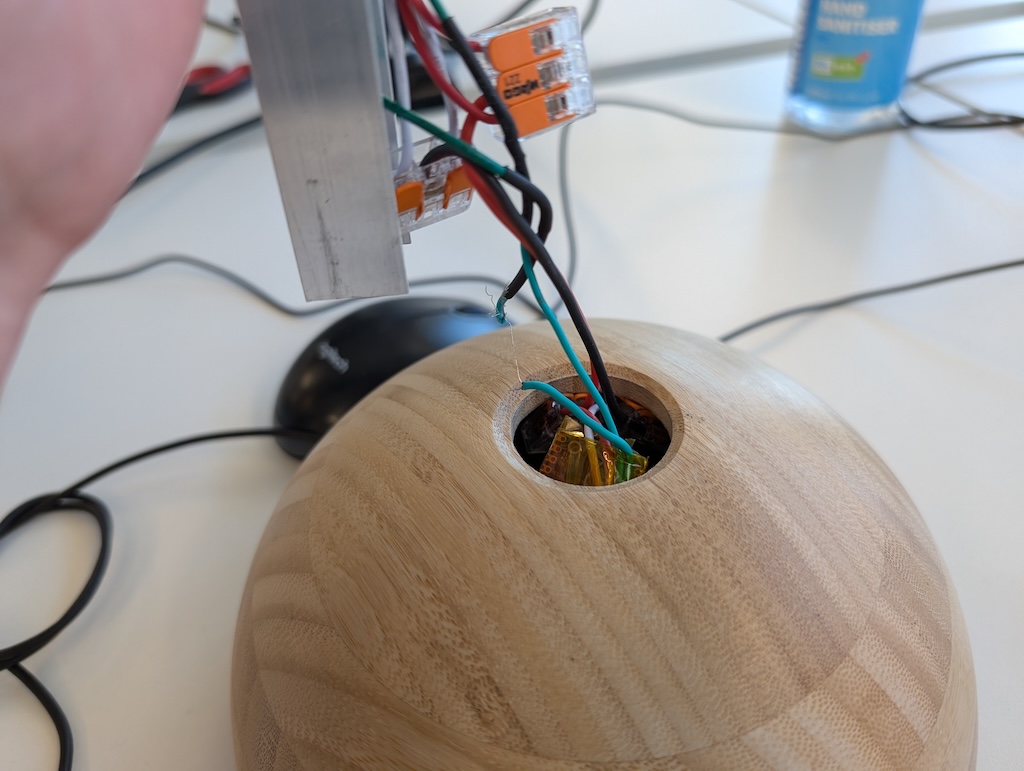
By a thread
The last but possibly most shocking discovery, actually happened after the conference. In my haste to put everything together, rather than use a removable fastener, I’d hot-glued the base of the stand into place. That meant that I’d had to shove all the wiring into the base, then blindly push the metal leg into the hole and hope that I didn’t accidently chop through any of the wires. Luckily, after a quick test, everything seemed fine.
It wasn’t until after the event, while I was making a few firmware tweaks based on learnings from the day, that I removed the metal leg from the base to access the micro-controller and realised just how close I’d come to disaster!
For anyone left worrying, without a looming deadline, I revisited the hot-glue situation before I put it back together again. The bottom can now easily be removed for significantly less stressful reassembly.
Conclusion
In the end, everything came together on the day and the mobiumata fulfilled its brief of being a flashy, shiny, interactive, conversation starter. And, it continues to do so today in the reception of Scott Logic’s Newcastle office. Please feel free to play with it if you’re ever passing through.
Projects like this are always satisfying to see through. Not only for the knowledge you expect to pick up along the way (embedded Rust, async Rust, etc.), but typically more interesting are the tidbits you didn’t expect to (e.g. the many failings of the human visual system, the perils of hot-glue, etc.). I also find it really rewarding when I build something that engages others, so for that I’d like to thank my colleagues who were suitably nerd-sniped when I setup mobiumata in the office (without any explanation).
One final anecdote from the build which reminded me of my place in the world was when I showed it to my 4-year old daughter. After a few minutes hacking on the firmware, I tempted her into coming to have a look. “Would you like to see something cool? I’ve built something covered in rainbows and it’s got your name on it!”. She placated me by getting up from her tea party and following me into the workshop. When she saw it her face immediately lit up… I was so proud… until she spoke…
“Daddy, you’ve made the sign from Rocky’s truck! Now there’s just one thing you need to do to make it really good. Just make it stay green!”
For those unacquainted with Paw Patrol, she was referring to the recycling sign on the side of his recycling truck…
Thanks for taking the time to read to the end. If you’d like to dig deeper into the code behind mobiumata, you can find it all on GitHub.