Sadly my time working with a colleague had come to an end and I wanted to give him a token of my appreciation. In these days of hybrid working, I thought what better way to show my appreciation to an infrequent Vim user, than to add another rarely useful peripheral to their bag!
Just what is a Vim clutch?
In case you’re not familiar with vim itself, a very quick recap. Vim is the successor to vi, a mode-based text editor released in the mid 70s and originally designed for the ADM-3A video display terminal. Its successor was released in the early 90s and inherits many of its divisive characteristics.
I find Vim tricky to use because of its unique keybindings which often see me reaching for a Vim cheat sheet. However, once upon a time they made a lot more sense. Specifically, when you were working on a ADM-3A keyboard -

The most obvious examples are the HJKL keys. Instead of inserting the corresponding letters, in Vim these keys move the cursor around the screen.
To insert letters in Vim, you must first leave normal mode and enter insert mode by pressing i. Conversely to stop inserting text and perform other actions, you must leave insert mode and enter normal mode by pressing ESC. This is referred to as mode-switching.
Whilst mode switching is unintuitive, after a period of adjustment, the real problem becomes an ergonomic one. On an ADM-3A keyboard the ESC key was easily at hand but on a modern keyboard, it’s either an uncomfortably long middle finger stretch or a full hand reposition.
At this stage most folk take the easy route out. They rebind the TAB or CAPS LOCK key to function as the ESC key and get back to being productive. But thankfully not everyone. A very special few have stepped back, looked down and spotted a whole pair of limbs that they weren’t making use of.
In other words, a Vim clutch is typically a repurposed keyboard/guitar pedal that enters insert mode when you press down on it and leaves it when you release it. This can and has been accomplished in a great many weird and wonderful ways. Let’s add another to that list.
Hardware
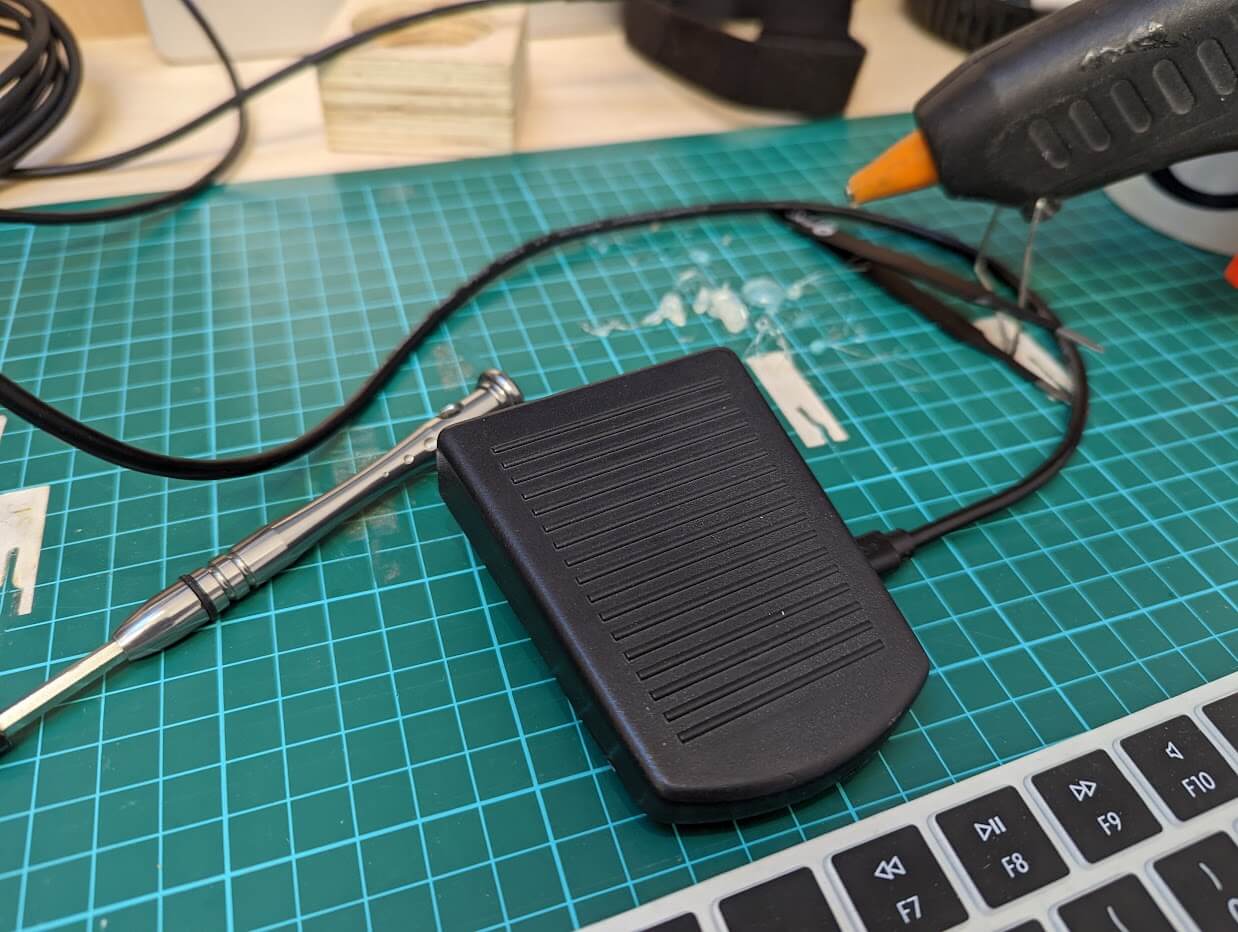
I picked up a cheap foot pedal switch on eBay and popped it open. Inside was a basic push-to-make switch wired up to the 3.5mm plug that came out the back of it. Rather than create a standalone adapter for this plug into, I wanted to keep everything self contained, so I opted to chop off the plug along with most of the wire.
Next it was a case of finding space inside to wedge a Rasberry Pi Pico into (the official Raspberry Pi 2040 microcontroller board) . Not only did it need to physically fit inside, but I also had to ensure that the USB port was accessible from the outside and that it didn’t obstruct the movement of the foot switch when a cable was plugged in.
Unfortunately there wasn’t an obvious solution. It would have been nice to reuse the existing cable hole but the switch was very much in the way. It might have been possible to use the USB pads on the back of the Pico to wire in a new USB socket on an extension. However, in the end it was easier to cut a new hole in the side of the base and delicately “reconfigure” the corners of the Pico board with some 60 grit sandpaper.
With the Pico in place it was time to check the Pico’s pin-out for a conveniently located pair of GPIO and ground pins. Pressing the switch will bridge these pins in a way that’s detectable in software on the microcontroller.
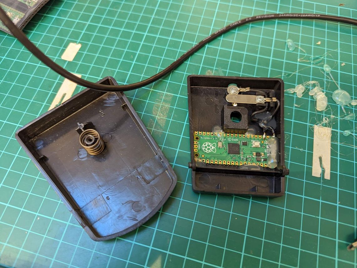
This is a glamour shot of the inside of the completed project. I definitely didn’t have the confidence to go gung ho with the hot glue at this stage!
Bootloader
My approach to any complex problem is to start with a base assumption that nothing works. Then introduce the smallest reasonable amount of unknown. Prove this new version works as expected and keep iterating up the stack until I have a working thing or need a break.
So let’s first assume either the microcontroller was already fried or, more likely, my soldering skills had somehow toasted it. To prove otherwise, I connected it to the laptop to see if the built-in USB bootloader fired up and mounted it as a RPI-RP2 volume.
It did not…
Luckily, I quickly realised I’d failed to follow my own advice. I hadn’t checked that the random USB cable I’d picked up had the data pins wired up. Only the power pins were wired up. This works great for charging but not for transferring data.
After further rummaging in a box of old cables, I found one that did have the data pins wired up. I connected it up and success - the RPI-RP2 volume showed up in Finder.
Project Template
Before starting to write my own software, I wanted to make sure the chip was working with some known good software. The chip can be programmed in a number of different languages but I chose Rust for the hacker news karma.
I cloned the rp-rs/rp2040-project-template which helpfully defaults to targeting the Pico. As I don’t have a debug probe, I followed the instructions in the readme for configuring cargo to use the alternative elf2uf2-rs runner, which allows programming via the USB bootloader.
The instructions seem a little out of date. At the top of the .cargo/config.toml file, you need to comment out the line runner = “probe-run –chip RP2040” and uncomment the line runner = “elf2uf2-rs -d”.
With that configured, I could run cargo run. Cargo did a little crates dance, built the project and transferred it onto the Pico. The Pico then rebooted itself, the template program loaded and unleashed the hello world of hardware, the blinking LED!
On macOS the Pico rebooting from the bootloader triggers a very annoying error message about not ejecting it properly. Thankfully you can ignore these but dismissing them every time is very annoying!
GPIO
Next on the list was to prove whether or not I could successfully read the state of the switch by modifying the software to turn the LED on only while the switch was depressed. Skipping past the setup code in the template project, here’s what the main loop looked like -
loop {
    info!("on!");
    led_pin.set_high().unwrap();
    delay.delay_ms(500);
    info!("off!");
    led_pin.set_low().unwrap();
    delay.delay_ms(500);
}
If you’re familiar with Rust, the calls to unwrap would typically indicate that set_high/low are fallible (can fail) and failure should explicitly be handled. However, in this case they are being invoked on a Result<(), Infallible> so can never actually fail. In a more serious context, I would consider using this crate which provides an unwrap_infallible method.
No matter your programming background, I think the above is intuitive enough. To make use of the switch I assumed I needed to grab a reference to the struct corresponding to that pin. Let’s see how that was done for led_pin -
let pins = bsp::Pins::new(
    pac.IO_BANK0,
    pac.PADS_BANK0,
    sio.gpio_bank0,
    &mut pac.RESETS,
);

let mut led_pin = pins.led.into_push_pull_output();
The led_pin was being retrieved from the bsp::Pins struct’s led field. Ignoring how the struct was created, as it was in the Board Support Package module, I assumed it was specific to our board (as opposed to the Hardware Abstraction Layer which would have been generic across all RP2040 boards). As the LED had the label LED on the board’s silkscreen, I assumed there would be a similarly named field for the GP0 label on the General Purpose Input Output pin I connected the switch to -
let mut switch_pin = pins.gpio0.into_pull_up_input();
Close enough! I also configured the pull-up/down input behaviour of the pin to allow me to reliably read it as 3.3V (the RP2040 supply voltage). Conversely, had I connected one side of the switch to 3.3V instead of ground, I could have configured the GPIO pin to be a pull-down input.
At this point I’d like to note the clever use of Rust’s ownership model to manage the microcontroller’s peripherals (all the non-CPU parts e.g. timers, GPIOs). In case you’re not familiar with it, the Rust compiler guarantees that a variable has exactly one owner. The API is making use of this guarantee to prove exclusive access to resources at compile-time. It does this by restricting the set of available operations to -
- Partitioning a variable representing a high-level grouping of peripherals into multiple variables representing the individual peripherals e.g.
bsp::Pins. - Swapping a variable representing not only a peripheral but also its current configuration, for another variable representing the peripheral configured in an alternative way e.g.
into_pull_up_input.
By only permitting access to peripherals in this manner, the compiler prevents two non-collaborating pieces of code from independently accessing a peripheral at runtime. Additionally, it prevents two collaborating pieces of code from sharing a peripheral if they require conflicting configurations.
Most of the setup code I skipped over earlier exists for this reason. Establishing a chain of custody for any peripherals that are used later in the code. The rest deals with overlaying the BSP configuration on the HAL.
Anyhow, enough Rust talk, let’s look at how I modified the code -
loop {
    let switch_state = switch_pin.is_low().unwrap();
    if switch_state {
        led_pin.set_high().unwrap();
    } else {
        led_pin.set_low().unwrap();
    }
}
As this was my second time loading software onto the board, the bootloader no longer runs by default. To get to the USB bootloader, I had to unplug the board and then while holding down the bootloader button, plug it in again. With this done, I used cargo run again to load the software onto the device. A quick reboot later and here’s what happened when I pressed the button -
USB HID
Before I could send keypresses, I needed to identify the board to the host as a USB Human Interface Device. Using the twitchy mouse example as a starting point, I first added the USB dependencies to cargo.toml -
usb-device= "0.2.9"
usbd-hid = "0.5.1"`
And some new imports and useful constants to main.rs -
// USB Device support
use usb_device::{class_prelude::*, prelude::*};

// USB Human Interface Device (HID) Class support
use usbd_hid::descriptor::generator_prelude::*;
use usbd_hid::descriptor::KeyboardReport;
use usbd_hid::hid_class::HIDClass;

const USB_HOST_POLL_MS: u8 = 10;

const KEY_I: u8 = 0x0c;
const KEY_ESC: u8 = 0x29;
The original example used interrupts rather than polling the USB peripheral. However, as I was already polling the switch, to keep things simple I also polled the USB peripheral. That meant I could skip the globals and simplify the setup code a little. I also changed the HID class from a mouse to a keyboard for obvious reasons and updated the device configuration strings -
// Set up the USB driver
let usb_bus = UsbBusAllocator::new(bsp::hal::usb::UsbBus::new(
pac.USBCTRL_REGS,
pac.USBCTRL_DPRAM,
clocks.usb_clock,
true,
&mut pac.RESETS,
));
// Set up the USB HID Class Device driver, providing Keyboard Reports
let mut usb_hid = HIDClass::new(&usb_bus, KeyboardReport::desc(), USB_HOST_POLL_MS);
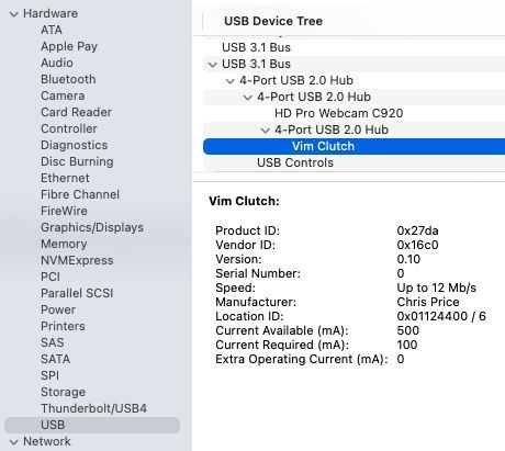
// Create a USB device with a fake VID and PID
let mut usb_dev = UsbDeviceBuilder::new(&usb_bus, UsbVidPid(0x16c0, 0x27da))
.manufacturer("Chris Price")
.product("Vim Clutch")
.serial_number("0")
.device_class(0)
.build();
loop {
usb_dev.poll(&mut [&mut usb_hid]);
}
Another reprogram of the board and a look at System Information to check that it shows up as expected -
Keyboard Reports
To send a key press to the host, you first need to send a KeyboardReport stating that a given key is active, followed by another stating that no keys are active. After sending each report, you must also wait a short delay to allow for the host to poll for the report -
fn send_key_press(
    usb_hid: &HIDClass<bsp::hal::usb::UsbBus>,
    delay: &mut cortex_m::delay::Delay,
    key_code: u8,
) {
    let mut keyboard_report = KeyboardReport {
        modifier: 0,
        reserved: 0,
        leds: 0,
        keycodes: [0; 6],
    };
    keyboard_report.keycodes[0] = key_code;
    usb_hid.push_input(&keyboard_report).unwrap();
    delay.delay_ms(USB_HOST_POLL_MS.into());

    keyboard_report.keycodes[0] = 0;
    usb_hid.push_input(&keyboard_report).unwrap();
    delay.delay_ms(USB_HOST_POLL_MS.into());
}
The push_input calls above are fallible so failure should explicitly be handled. In a more serious context, I would dedicate more time to thinking about the best way to handle this!
Finally, I added some code to track the state of the switch so that I could detect changes and then dispatch the key presses as appropriate -
let mut switch_state = switch_pin.is_low().unwrap();

loop {
    usb_dev.poll(&mut [&mut usb_hid]);

    let previous_switch_state = switch_state;
    switch_state = switch_pin.is_low().unwrap();

    match (previous_switch_state, switch_state) {
        (true, false) => {
            info!("normal mode!");
            led_pin.set_low().unwrap();

            send_key_press(&usb_hid, &mut delay, KEY_ESC);
        }
        (false, true) => {
            info!("insert mode!");
            led_pin.set_high().unwrap();

            send_key_press(&usb_hid, &mut delay, KEY_I);
        }
        _ => {}
    }
}
The moment of truth -
Conclusion
Building a Vim clutch pedal has definitely hit the brief of being a fun introduction to Rust programming on the Raspberry Pi 2040 Pico. As much as I built the pedal for a joke, I can’t deny that there is something very satisfying about using it.
I think this is a general feeling I get with hardware projects. There’s just something about the tactile nature of them that, despite them being mostly software which I work with all the time, makes them feel much more rewarding that a typical software project. Having said that, I don’t think I’ll be rushing to build myself one. I’m happy with Visual Studio Code!
If you’d like to build your own or look at the code in more detail, it’s available on GitHub. Just one final hardware tweak before I hand over the gift. The secret to longevity in any successful hardware project. The liberal application of hot melt glue -