
In my last blog post, I demonstrated my ray tracer for the BBC Micro:Bit. In that post, I talked a little about what a ray tracer is, but didn’t discuss how you actually implement one. If you don’t know what a ray tracer is, make sure you read that post first.
This post discusses a ray tracer in detail, talking you through the computation step-by-step. It’s not the most advanced ray tracer - in fact it’s about as simple as they come. It fires one ray per pixel, and doesn’t support reflection or refraction. However, you should be able to adapt it to your needs once you understand the maths.
I deliberately haven’t included any code samples. Instead, I explain in words, maths, and pictures. That probably seems scary, but trust me when I say that ray tracing just isn’t that complicated. If I included code samples, you would probably just copy them and not really understand what was going on.
By the end of this post, you should have an intuitive understanding of how ray tracers work. You should be able to write the code yourself, and more advanced readers will be able to extend their implementation with extra features.
Step 1: Define your Scene
Ray tracers simulate light rays to render a 3D scene. Before we can start doing that, we need to define the scene that we want to render.
In our simple implementation, the scene contains one camera and many triangles. We only use triangles in our scene because they are the simplest shape to render. We can convert more complex shapes into triangles in a process called triangulation
Each triangle \(t\) is a set of 3 coordinates \(\left\{ t_1, t_2, t_3 \right\}\).
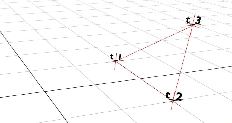
Each coordinate is a 3D coordinate \(\left\{ x, y, z \right\}\).
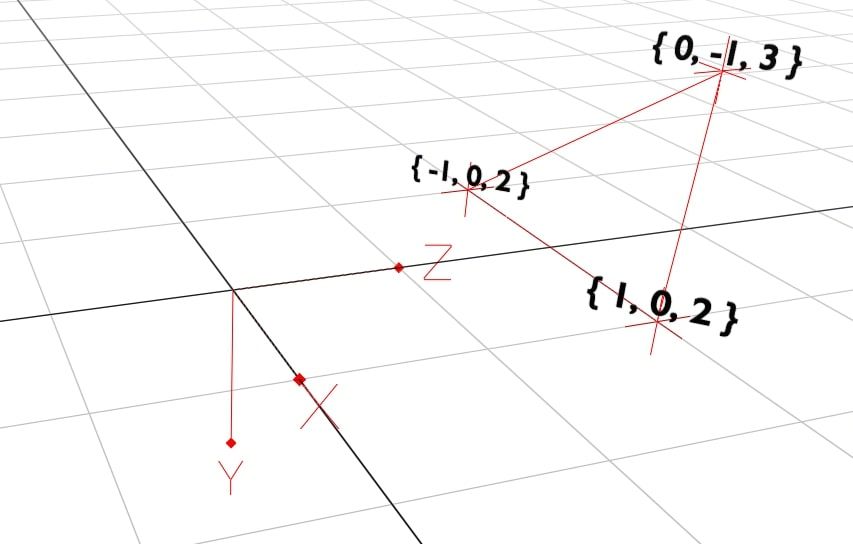
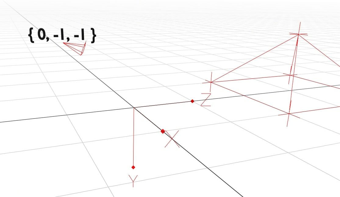
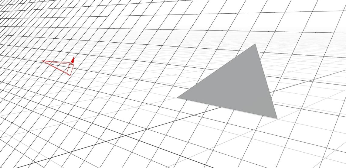
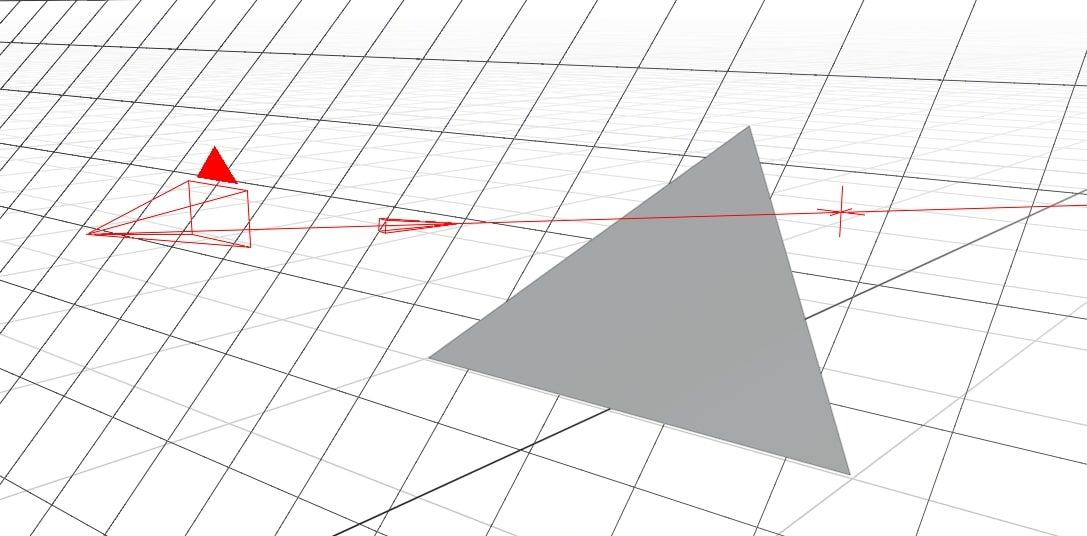
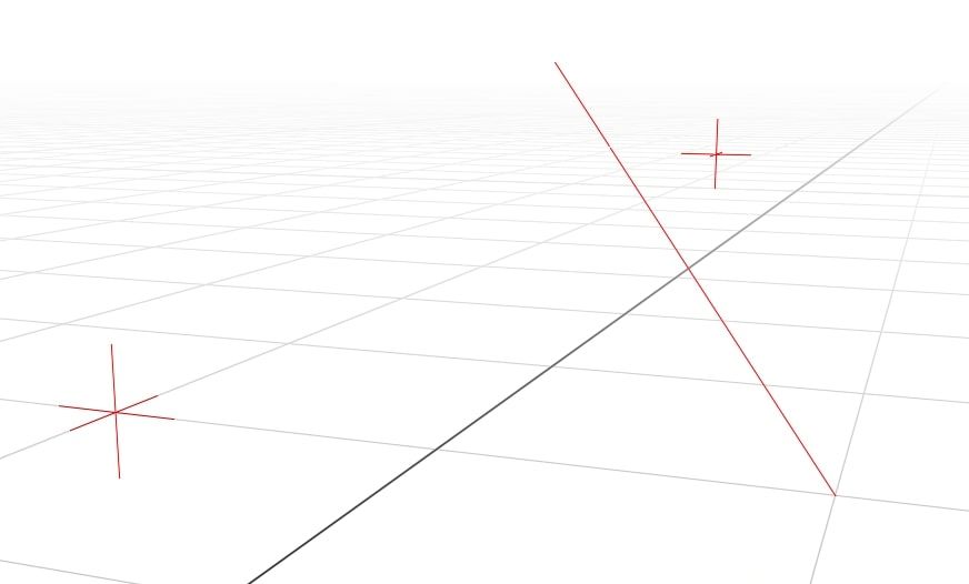
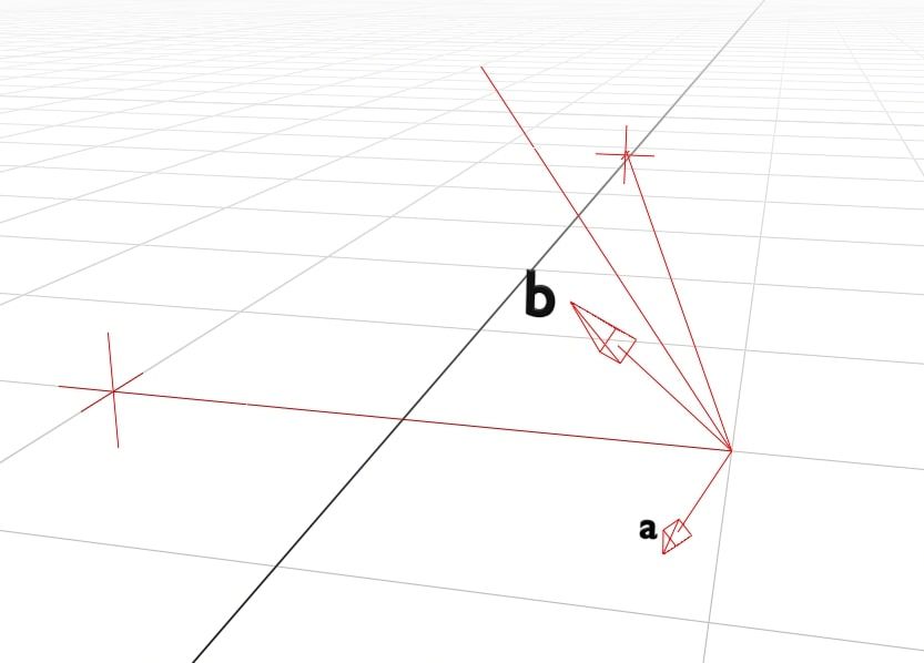
We add four triangles in a pyramid shape and the camera. The camera’s position is also a 3D coordinate. It dictates where we are looking in the scene.
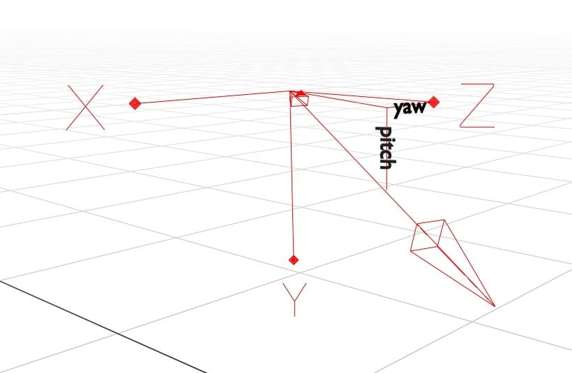
The camera is special because it has both a position and a direction. This allows us to turn the camera and look around the scene. The camera’s rotation is given as \(\theta_y\) (yaw) and \(\theta_p\) (pitch). Yaw handles the left-right rotation, while the up-down rotation is determined by the pitch. Together, these let the camera look in any direction.
Step 2: Calculate the Triangle Planes
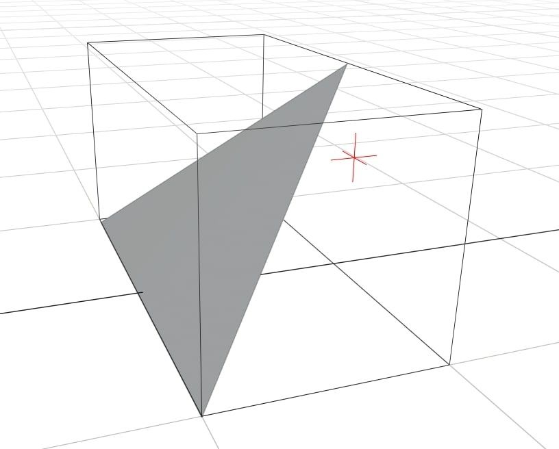
Triangles are flat and two-dimensional. We can imagine a triangle as a small section of an infinite plane.
We describe a plane as \(\bar{p} = \left\{ a, b, c, k \right \}\). Any values of \(\left\{ x, y, z \right\}\) that satisfy \(aX + bY + cZ + k = 0\) are on the plane, and vice-versa.
The \(a\), \(b\), and \(c\) components of the plane decide its orientation. We can calculate them by finding the angle of the plane’s normal line. The normal line is the line that is orthogonal (at a right angle) to the plane.
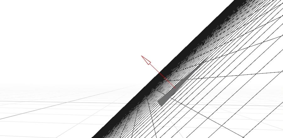
To get the angle of the normal, we will use the cross-product of two vectors. The cross-product is an algebraic function which, given two vectors, outputs a new vector which is orthogonal to both.
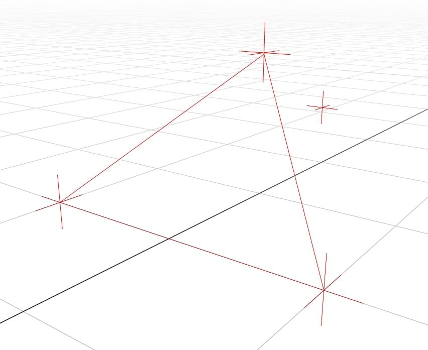
To find the plane’s normal line we need two vectors on the plane that cross. We can pick any two sides of the triangle.
I will use the two lines crossing at \(t_1\). We can calculate the angle of those two lines by looking at the difference in coordinates from one end to the other:
\[\bar{a} = t_2 - t_1\\ \bar{b} = t_3 - t_1\\\]For anyone that’s new to vectors, subtracting them works like this:
\[\bar{a} - \bar{b} = \begin{Bmatrix} \bar{a}_x - \bar{b}_x\\ \bar{a}_y - \bar{b}_y\\ \bar{a}_z - \bar{b}_z\\ \end{Bmatrix}\]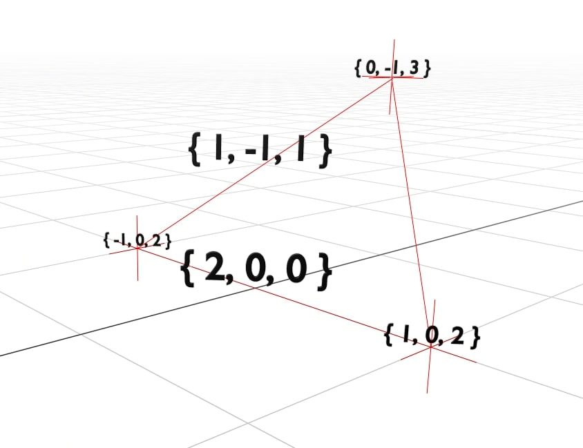
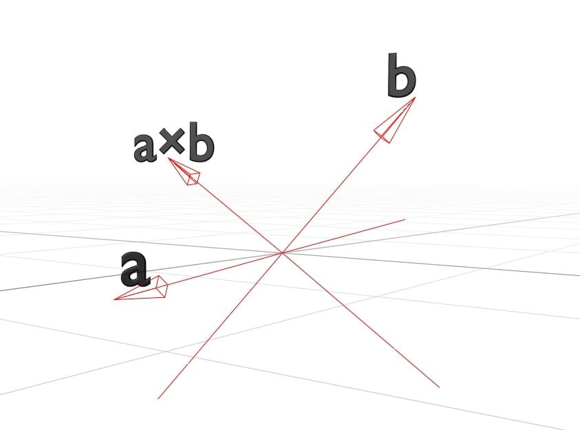
Now that we have our two lines \(\bar{a}\) and \(\bar{b}\), we can calculate the normal line as \(\bar{a} \times \bar{b}\). This is \(\times\), the cross product operator.
I’m not new to vectors, but I certainly can’t remember how to do a cross product. For anyone in the same camp, here’s how it works:
\[\bar{a} \times \bar{b} = \begin{Bmatrix} \bar{a}_y \cdot \bar{b}_z & - & \bar{a}_z \cdot \bar{b}_y\\ \bar{a}_z \cdot \bar{b}_x & - & \bar{a}_x \cdot \bar{b}_z\\ \bar{a}_x \cdot \bar{b}_y & - & \bar{a}_y \cdot \bar{b}_x\\ \end{Bmatrix}\]If you want a more in-depth explanation of how it works, try this ‘Math is Fun’ page. I’m not ashamed to say that I spent a long time on that site. It may be for children, but it sure is helpful!
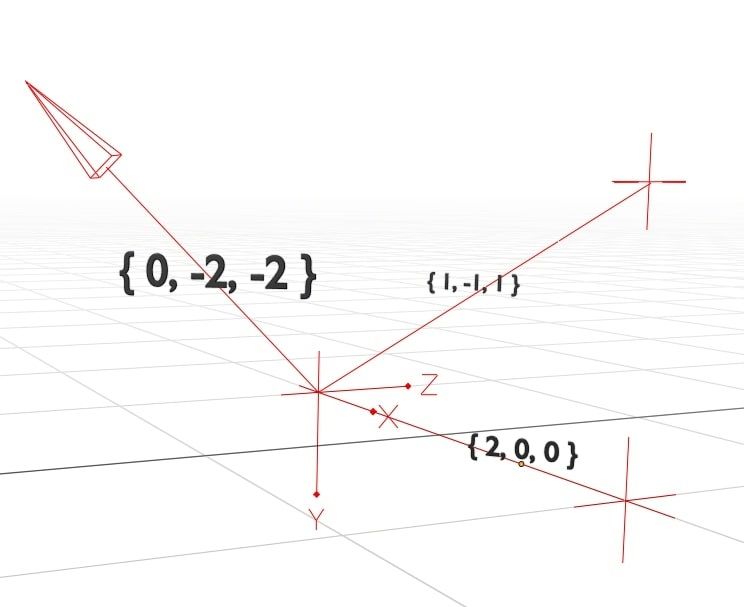
Using the cross product, we now have the angle of the normal line \(\bar{n} = \left\{ 0, -2, -2 \right\}\). The values of \(\bar{n}\) map to the \(\left\{ a, b, c \right\}\) components of the plane.
To calculate the final component, \(k\), we need to go back to the plane formula:
\[a \cdot X + b \cdot Y + c \cdot Z + k = 0\]We can substitute in our values from \(\bar{n}\):
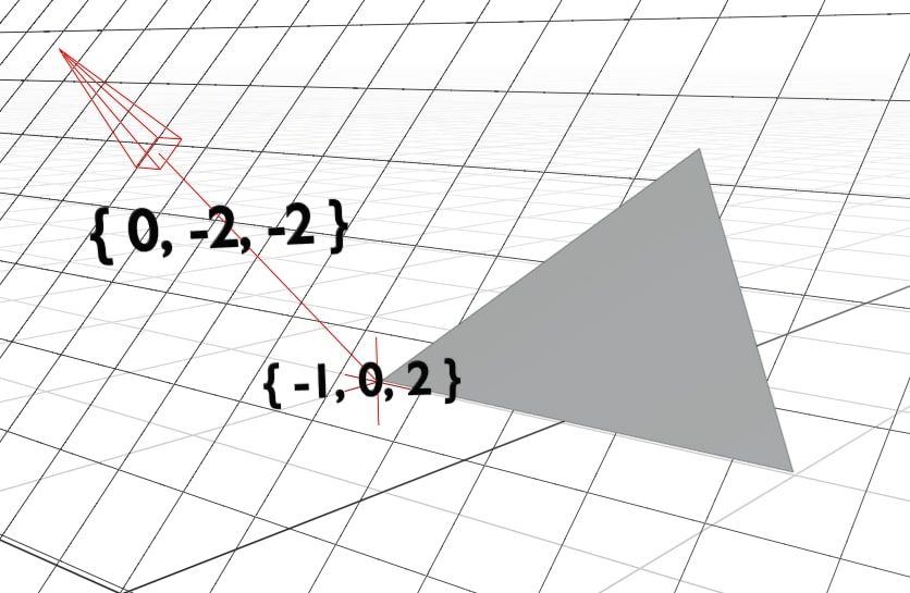
\[\bar{n}_x \cdot \bar{s}_x + \bar{n}_y \cdot \bar{s}_y + \bar{n}_z \cdot \bar{s}_z + k = 0\] \[\bar{n} \cdot \bar{s} + k = 0\] \[k = - \bar{n} \cdot \bar{s}\]Here, \(\bar{s}\) is simply any point on the plane. The last two lines are using the dot product, \(\bar{a} \cdot \bar{b}\) for conciseness. It’s defined as:
\[\bar{a} \cdot \bar{b} = \begin{Bmatrix} \bar{a}_x \cdot \bar{b}_x\\ \bar{a}_y \cdot \bar{b}_y\\ \bar{a}_z \cdot \bar{b}_z\\ \end{Bmatrix}\]Now we know that \(k = - \bar{n} \cdot \bar{s}\), we can calculate it by substituting the value of our normal line \(\bar{n}\) and any point on the plane \(\bar{s}\). Pick your favourite corner of the triangle and use that.
In our case, this becomes:
\[k = - \left( 0 \cdot -1 + -2 \cdot 0 + -2 \cdot 2 \right)\\ k = 2 \cdot 2\\ k = 4\]Meaning the overall vector for the plane is:
\[\bar{p} = \begin{Bmatrix} \bar{n}_x\\ \bar{n}_y\\ \bar{n}_z\\ - \bar{n} \cdot \bar{c}\\ \end{Bmatrix} = \begin{Bmatrix} 0\\ -2\\ -2\\ 4\\ \end{Bmatrix}\]Referring back to the original formula for the plane, we can substitute in our values to get \(0x - 2y - 2z + 4 = 0\) or put simply \(y + z = -2\). That’s it, we have calculated the formula for the plane!
Step 3: Calculate the Ray Lines
It’s time to start simulating the rays. The vector representation of a line, including both position and angle, is:
\[\lambda \bar{m} + \bar{s}\]\(\bar{s}\) is the origin point of the ray. In our case, it is always the same as the camera coordinates. \(m\) is the angle of the ray. It specifies how the \(x\), \(y\), and \(z\) coordinates change as we move along the line. The \(\lambda\) parameter specifies how far along the line we are.
You were probably taught a similar formula for 2D graphs in school, \(y = mx + c\). That is equivalent to saying:
\[\begin{Bmatrix} x\\ y\\ \end{Bmatrix} = \lambda \cdot \begin{Bmatrix} 1\\ m\\ \end{Bmatrix} + \bar{c}\]In other words, for each \(1\) that \(x\) increases, \(y\) increases by \(m\). You can move along the line using \(\lambda\). It is simple to see how this gets extended to work in 3D.
Finding the origin of the ray, \(\bar{s}\), is easy. All rays start at the camera position \(\bar{c}\), so we just use that.
Calculating \(\bar{m}\), the line’s angle, is more complex. This is the ratio of how each coordinate changes as we move along the line.
If \(\bar{m}\) was \(\left\{ 1, 2, 3 \right\}\) then for each increase in \(x\), we would see twice the increase in \(y\) and three times the increase in \(z\). Since \(\bar{m}\) is just a ratio, it doesn’t matter whether we say \(\left\{ 1, 2, 3 \right\}\) or \(\left\{ 100, 200, 300 \right\}\).
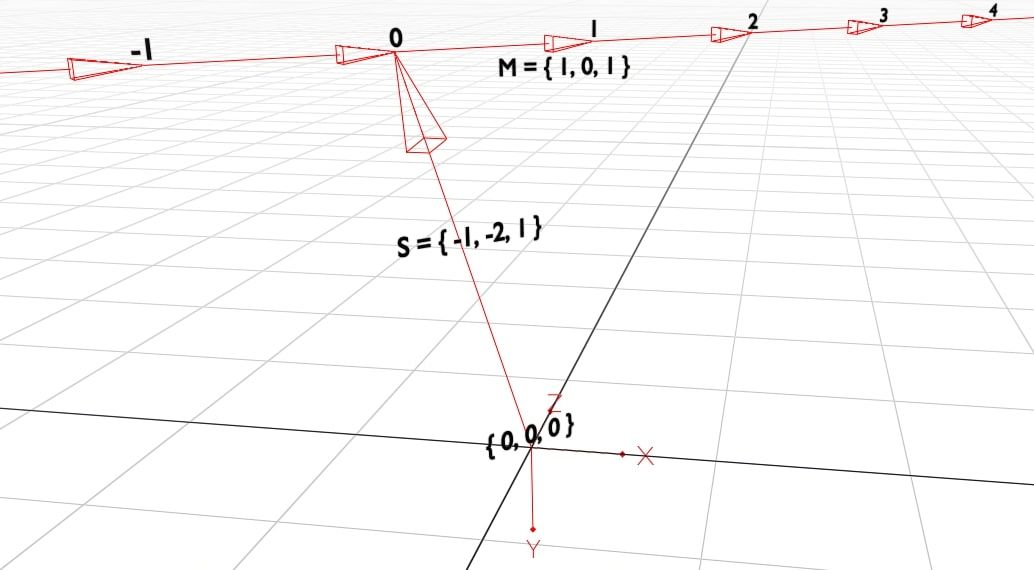
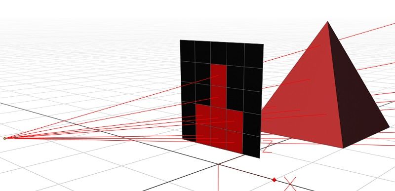
We can find \(\bar{m}\) by looking at how the coordinates change along a known portion of the line. We will look at the portion of the line from the camera to the view plane. The view plane is a grid that sits \(1 \text{m}\) in front of the camera. Each cell in the grid is one pixel that we want to paint on the screen.
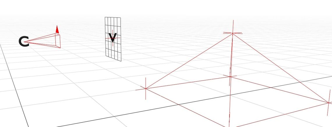
For now, we will just consider the simplest case. The camera has no rotation, and is just looking straight ahead (in the \(z\) direction). We are calculating the angle of the center ray, which goes through the centermost pixel in the grid.
In that case, the change in coordinates between the camera’s position and the center of the view plane is simply \(\bar{m} = \left\{ 0, 0, 1 \right\}\). In this example, we will treat the view plane as having a fixed width of \(0.5 \text{m}\). Since the screen is \(5 \times 5\) pixels, each pixel has a width and height of \(0.1 \text{m}\).
For every pixel right of the center, we must add \(0.1 \text{m}\) to \(\bar{m}_x\). That means that for the pixel \(\left\{ p_x, p_y \right\}\) \(\left( 2, 2 \right)\) being the center, \(\bar{m}\) is simply:
\[\bar{m} = \begin{Bmatrix} 0.1 \cdot (p_x - 2)\\ 0.1 \cdot (p_y - 2)\\ 1\\ \end{Bmatrix}\]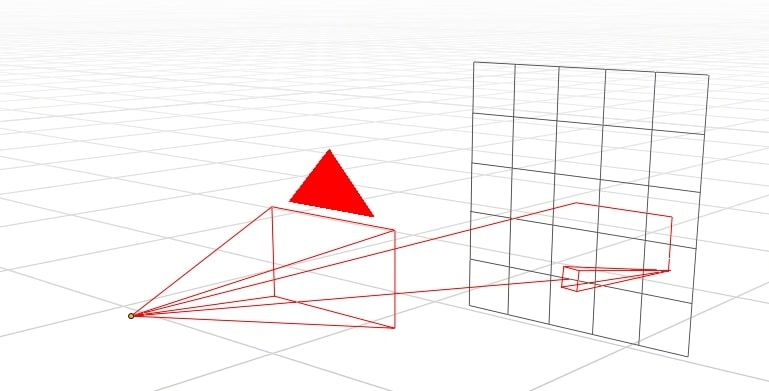
However, this ignores the direction of the camera. Thankfully, rotating vectors is quite simple. We can simply rotate \(\bar{m}\) to match the rotation of the camera.
To rotate a vector about the \(y\) axis (yaw), we do:
\[rot_y \left( \bar{v}, \theta \right) = \begin{Bmatrix} \bar{v}_x \cdot \cos{\theta} & + & \bar{v}_z \cdot \sin{\theta}\\ & \bar{v}_y &\\ -\bar{v}_x \cdot \sin{\theta} & + & \bar{v}_z \cdot \cos{\theta}\\ \end{Bmatrix}\]And about the \(x\) axis (pitch), we do:
\[rot_x \left( \bar{v}, \theta \right) = \begin{Bmatrix} & \bar{v}_x &\\ \bar{v}_y \cdot \cos{\theta} & - & \bar{v}_z \cdot \sin{\theta}\\ \bar{v}_y \cdot \sin{\theta} & - & \bar{v}_z \cdot \cos{\theta}\\ \end{Bmatrix}\]Therefore, given yaw \(\theta_y\) and pitch \(\theta_p\):
\[\bar{m}^{\theta_p}_{\theta_y} = rot_x \left( rot_y \left( \begin{Bmatrix} 0.1 \cdot \left( p_x - 2 \right)\\ 0.1 \cdot \left( p_y - 2 \right)\\ 1\\ \end{Bmatrix}, \theta_y \right), \theta_p \right)\]Now that we know both \(\bar{m}\) and \(\bar{s}\), we can calculate the coordinates of any point along the ray’s path.
Step 4: Intersect Rays with Planes
We’re finally ready to simulate our light rays. We know where our light rays start, where they’re going, and everything they might hit. All that’s left to do is to actually simulate the path and find out what each ray hits.
More precisely, we need to find the intersection point of each pairwise ray/plane combo. To be even more precise, for each pairwise combo of ray \(\bar{r} = \lambda \bar{m} + \bar{s}\) and plane \(\bar{p} = \left\{ a, b, c, k \right\}\), what is the intersection point \(\bar{i}\)?
Obviously, \(\bar{i}\) must be on both \(\bar{r}\) and \(\bar{p}\). We can substitute \(\bar{i}\) into the formula for \(\bar{r}\) to get:
\[\bar{i} = \lambda \bar{m} + \bar{s}\\ \bar{i} = \begin{Bmatrix} \lambda \cdot \bar{m}_x + \bar{s}_x\\ \lambda \cdot \bar{m}_y + \bar{s}_y\\ \lambda \cdot \bar{m}_z + \bar{s}_z\\ \end{Bmatrix}\]And we can do the same for \(\bar{p}\) to get:
\[a \cdot \bar{i}_x + b \cdot \bar{i}_y + c \cdot \bar{i}_z + k = 0\]Then we substitute in the values of \(\bar{i}\) from above:
\[a \cdot (\lambda\bar{m}_x + \bar{s}_x) + b \cdot (\lambda\bar{m}_y + \bar{s}_y) + c \cdot (\lambda\bar{m}_z + \bar{s}_z) + k = 0\]Which can then be rearranged to solve for \(\lambda\):
\[a\lambda\bar{m}_x + a\bar{s}_x + b\lambda\bar{m}_y + b\bar{s}_y + c\lambda\bar{m}_z + c\bar{s}_z + k = 0\] \[a\lambda\bar{m}_x + b\lambda\bar{m}_y + c\lambda\bar{m}_z = -a\bar{s}_x - b\bar{s}_y - c\bar{s}_z - k\] \[\lambda \left( a\bar{m}_x + b\bar{m}_y + c\bar{m}_z \right) = -a\bar{s}_x - b\bar{s}_y - c\bar{s}_z - k\] \[\lambda = - \frac{a\bar{s}_x + b\bar{s}_y + c\bar{s}_z + k}{a\bar{m}_x + b\bar{m}_y + c\bar{m}_z}\] \[\lambda = - \frac{\left\{ a,b,c \right\} \cdot \bar{s} + k}{\left\{ a,b,c \right\} \cdot \bar{m}}\]Now that we know \(\lambda\), we can substitute it back into the definition above to calculate the coordinates of \(\bar{i}\).
Step 5: Filter Intersection Points
Not all intersection points are actually valid. All we know about \(\bar{i}\) is that it is on the same plane as a triangle. However, we only care about the ones that are actually inside the triangle.
Before performing any other checks, note that \(\lambda \geq 0\). If your \(\lambda\) value is negative, you can stop early. That plane cannot get hit by the ray, as the intersection point is behind the camera.
Then, we can do a quick sanity check, making sure that \(\bar{i}\) is inside the bounding box of the triangle. If \(\bar{i}_x \lt \text{min}_x \left( t_1 , t_2 , t_3 \right)\) then \(\bar{i}\) cannot be inside the triangle as it is too far left. Repeat this for each combination of \(\text{min}\) or \(\text{max}\) and \(x\), \(y\), or \(z\).
We do that first because it’s much faster than the real check and we can often exit early. If \(\bar{i}\) is inside the bounding box, we need to do a full check, which works like this:
\(t\) has 3 sides. We know that \(\bar{i}\) is inside the triangle if:
- \(\bar{i}\) and \(t_1\) are on the same side of \(t_2 \rightarrow t_3\)
- \(\bar{i}\) and \(t_2\) are on the same side of \(t_1 \rightarrow t_3\)
- \(\bar{i}\) and \(t_3\) are on the same side of \(t_1 \rightarrow t_2\)
Intuitively, that makes sense.
To check whether \(\bar{i}\) and \(t_1\) are on the same side of the line \(t_2 \rightarrow t_3\), we do:
\[\bar{v} = t_2 - t_3\\ \bar{a} = \bar{v} \times \left( \bar{i} - t_3 \right)\\ \bar{b} = \bar{v} \times \left( t_1 - t_3 \right)\\ c = \bar{a} \cdot \bar{b}\\ c > 0\\\]This uses both the cross product and the dot product. The cross product has a special property that \(\bar{a} \times \bar{b}\) is the same as \(\bar{b} \times \bar{a}\) but in the opposite direction.
This goes further, and says that the direction of \(\bar{a}\) depends on which side of \(\bar{v}\) that \(\bar{i}\) is on. If \(\bar{i}\) and \(t_1\) are on the same side of \(\bar{v}\) then the angle between them will be \(< 90^{\circ}\). If they are on different sides, the angle will be \(> 90^{\circ}\).
When the dot product is positive, the angle between the two vectors is \(< 90^{\circ}\), meaning they must have been on the same side.
if \(c \geq 0\) then \(\bar{i}\) and \(t_1\) are on the same side. We repeat that for each of the three sides of the triangle. Any intersection points that are not in the triangle can be discarded.
Step 6: Rasterise the Rays
Each ray can only intersect with one triangle, so we need to find the triangle that gets hit first. To calculate the distance that the ray travelled, we can use Pythagoras’ theorem in 3D:
\[d = \sqrt{\left( \bar{i}_x - \bar{s}_x \right)^2 + \left( \bar{i}_y - \bar{s}_y \right)^2 + \left( \bar{i}_z - \bar{s}_z \right)^2 }\]For our simple implementation, we will set each pixel’s brightness to \(\frac{1}{d}\), meaning pixels that are closer to the camera are brighter. Any rays that don’t intersect result in a black pixel.
Conclusion
That’s it! You now know everything you need to, and can write your own ray tracer. If you want to know more about 3D rendering, make sure you have a look at these:
If you are still desperate for some example code, you can look at the code from my last post. Either way, you really should give it a try yourself first.
Once you’ve finished your basic ray tracer, here’s some extra features you could add, from easiest to hardest:
- Colour each triangle a different colour
- Send multiple rays per pixel and average the result
- Change the shape of the view plane to a dome
- Optimise your code, can it run at 60fps?
- Allow some triangles to behave like mirrors
- Add transparent materials and simulate refraction
- Add light sources to your scene, and render a shadow
- Add a black hole to the scene and simulate gravitational lensing
If you do write your own ray tracer, please show me on twitter (especially if you implement gravitational lensing, you absolute madlad)