
Writing emulators that bring old computer hardware back to life is a popular hobby, and one that I have been enjoying recently through my own goal of writing an Atari 2600 emulator. However, writing a CPU emulator can get a little repetitive and tedious, so I thought I’d explore a different approach - generating the CPU emulation code from a specification rather than manually translating it. This blog post shares the fruitful results.
Building an Atari 2600 Emulator
The Atari 2600 was a highly popular console in the late 70s and early 80s, bringing games like Pong, Breakout and Space Invaders into people’s homes. At the time hardware (and notably memory) costs were very high, so in order to create an affordable console, the team behind the 2600 had to get quite creative. To understand just how creative this machine was, I’d highly recommend reading the book Racing the Beam - the 2600 had so little memory that it didn’t have a conventional video RAM (a region of memory mapped direct to the screen), instead the various registers that effect the ‘pixels’ of the image were updated as the TV scanned each frame!
Since reading this book I’ve always wanted to have a go at emulating a 2600 in order to learn more about its hardware, and a few months back I embarked on this journey.
I decided to write the emulator using AssemblyScript, a TypeScript-derived language that compiles to WebAssembly since it has been a couple of years since I last tried it out and I am keen to see how it has evolved.
A fairly standard approach to writing a computer emulator is to ‘build’ the CPU first, then start tackling the hardware that surrounds it. However, my main interest and motivation was to explore how the 2600 ‘races the beam’, more specifically the relationship between the CPU (Central Processing Unit) and the TIA (Television Interface Adapter); so instead I started to build the two in parallel, implementing just enough CPU instructions to support the TIA functions.
Fortunately there is a lot of great documentation available for this console, most notably the book Atari 2600 Programming for Newbies. I have been reading that book chapter-by-chapter, implementing the emulator features I need to support each example in turn.
Here you can see the progression as I’ve implemented the various scanline synchronisation features, background colours and asymmetrical playfield graphics:
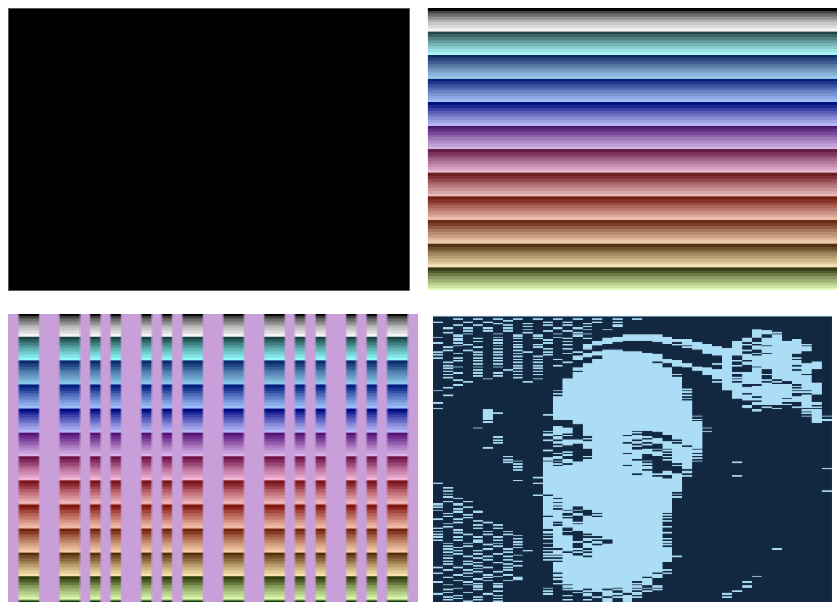
Next stop … sprites!
However, I’d reached a stage where it made sense to tackle the 6502 CPU (or more correctly the 6507, the same chip in a smaller package), and implement its instruction set in their entirety, and that is what the blog post primarily focusses on.
As an aside, if you are planning on having a go at writing your own emulator, the Atari 2600 is not an easy starting point. Most people familiarise themselves with the basic concepts of emulation via the much simpler CHIP-8. I did just that a little while back, writing a CHIP-8 emulator in Rust.
Building a 6502 emulator
The Atari 2600 uses a MOS 6507 as its CPU, a 6502 in a smaller package, cutting costs and reducing the addressable memory range. I started tackling this emulator in exactly the same way that I did with the CHIP-8. Structurally these emulators all look the same; read the next instruction from memory, switch on the opcode, read any associated operands from memory or registers, perform the operation then write to the appropriate location. It’s not a particularly challenging task, however, with the 52 instructions that the 6502 supports it is a little tedious!
Let’s delve a little deeper into what this task actually entails.
I’m using one of the many online reference sources for the 6502 instruction set, this particular one stands out as being quite concise and structured (which matters later on).
Here’s an example instruction, AND, a bitwise and operation applied to the value currently held in the accumulator (one of the three CPU registers):
AND  AND Memory with Accumulator

     A & M -> A                     N Z C I D V
                                    + + - - - -

     addressing    assembler    opc  bytes  cyles
     --------------------------------------------
     immediate     AND #oper     29    2     2
     zeropage      AND oper      25    2     3
     zeropage,X    AND oper,X    35    2     4
     absolute      AND oper      2D    3     4
     absolute,X    AND oper,X    3D    3     4*
     absolute,Y    AND oper,Y    39    3     4*
     (indirect,X)  AND (oper,X)  21    2     6
     (indirect),Y  AND (oper),Y  31    2     5*
Looking at the above specification, we can see that it provides the following information:
- The operation mnemonic,
AND, and a brief summary - A pseudocode representation of the operation itself
A & M -> A, read, bitwise-and and assign - A mini table, with headings -
N Z C I D V, that denotes the effect on the CPUs various status registers. In this case the negative and zero registers are updated based on the result of the operation.
Below this information is a table that details the various addressing modes that this instruction supports. In each case the operation is the same, however, the source of the operand is different. For example immediate mode uses the value of the operand directly (i.e. the byte that follows the AND opcode in program memory), whereas the absolute,X mode operand is a 16-bit address, which is combined with the X register value, giving the address of the value to ‘AND’ with the accumulator.
These various addressing modes require different numbers of reads and writes and as a result they require a different number of clock cycles in order to complete, as detailed in the cycles columns. Furthermore, the cycles for some instructions may vary depending on the values involved at runtime - in this instance the asterisk * denotes that an extra cycle is required if a page boundary is crossed. From the perspective of writing an Atari 2600 emulator, getting this right is vital, as these clock cycles elapse the TV ‘beam’ is racing!
This specification, which details just one of the 52 instructions, packs in a lot of information, and in my initial implementation resulted in quite a lot of emulation code and associated unit tests.
After implementing a handful of these I took the obvious step of looking for patterns, both in terms of the specification itself and simple refactoring opportunities in the code I was writing. However, despite trying various techniques (including peeking at other people’s implementations in JavaScript, Rust and C#) I couldn’t find a pattern I was happy with. To be more specific, I couldn’t find a pattern that allowed me to easily determine that my implementation correctly implemented the specification via visual inspection, which frustrated me!
It was at this point that the thought struck me, rather than manually translating the specification into code, this is a process I could automate. My hope was that it would be easier to implement, and be sure of the correctness, of this translation process than to verify the correctness of the emulator implementation. In other words, if the specification is correct, and the translation process is correct and error free, the emulator it generates must be correct also.
Code generation
The 6502 specification is a ~600 line text file which is in some senses a Domain Specific Language (DSL), it makes sense to employ a conventional pattern for compiling (or transpiling) this into the CPU emulator implementation. I’ve covered this topic before in an earlier blog post which explores the standard tokeniser-parser-emitter pattern via the creation of my own language that targets WebAssembly. In this case the ‘language’ is more rigid in structure, and a tokeniser wouldn’t offer much advantage, so here I opted for a simpler two-phase parser-emitter structure.
Parser
The role of the parser is to output the Abstract Syntax Tree (AST). In this context the main purpose of this step is to read the specification and generate an array of instruction objects, each containing the relevant information that describes its function.
There is nothing terribly notable about the parser implementation, it is 170 lines of TypeScript code which is mostly concerned with string wrangling. You can view the code on GitHub if you are interested.
Here’s the parser output for the AND instruction:
{
  "name": "AND",
  "type": "assignment",
  "expression": "A & M",
  "assignee": "A",
  "description": "AND Memory with Accumulator",
  "flags": {
    "zero": "Modified",
    "negative": "Modified"
  },
  "addressingModes": [
    {
      "opcode": "29",
      "cycles": 2,
      "mode": "Immediate",
      "cycleModifier": "None"
    },
    {
      "opcode": "25",
      "cycles": 3,
      "mode": "Zeropage",
      "cycleModifier": "None"
    },
    {
      "opcode": "35",
      "cycles": 4,
      "mode": "Zeropage,X",
      "cycleModifier": "None"
    },
    {
      "opcode": "2D",
      "cycles": 4,
      "mode": "Absolute",
      "cycleModifier": "None"
    },
    {
      "opcode": "3D",
      "cycles": 4,
      "mode": "Absolute,X",
      "cycleModifier": "PageBoundaryCrossed"
    },
    {
      "opcode": "39",
      "cycles": 4,
      "mode": "Absolute,X",
      "cycleModifier": "PageBoundaryCrossed"
    },
    ...
  ],
}
An important element to note is the type property, which in this case is assignment. The parser identifies the instruction type, other examples include branch and test, which broadly describes the type of operation this instruction represents and as a result the ‘shape’ of the code that is generated.
Also, the expression property in this case has the value A & M. I could have also parsed these expressions into a nested AST, however the expressions are so trivial that this wouldn’t have added much value.
Generator
The generator / emitter takes the AST output from the parser and generates the resultant emulator code, which in this case is written in AssemblyScript.
The generator iterates over each of the instructions, calling the following generateInstruction for each:
const generateInstruction = (instruction: Instruction) =>
  instruction.addressingModes
    .map(address => {
      switch (instruction.type) {
        case "assignment":
          return generateAssignment(instruction, address);
        case "branch":
          return generateBranch(instruction, address);
        case "test":
          return generateTest(instruction, address);
        case "empty":
          return generateEmpty(instruction, address);
        case "jump":
          return generateJump(instruction, address);
        case "push":
          return generatePush(instruction, address);
        case "pop":
          return generatePop(instruction, address);
      }
    })
    .join("\n");
This iterates over each of the addressing modes for the instruction, invoking a generator based on the instruction type.
Here’s an example generator, in this case for the assignment type following the example of the AND instruction:
const generateAssignment = (
  instruction: AssignmentInstruction,
  address: AddressingMode
) => `
  case 0x${address.opcode}: /* ${instruction.name} */ {
    ${applyAddressingMode(address.mode)}
    const result: u16 = ${replaceRegisters(instruction.expression)};
    ${setFlags(instruction.flags)}
    ${assignValue(instruction.assignee, address.mode)}
    ${handleCycles(address)};
  }
  break;`;
This code generates the required case statement for this specific opcode (a combination of instruction and addressing mode). The body of the code ‘applies’ the addressing mode to locate the operand value, performs a simple transformation of the expression, A & M, sets status flags, assigns the resultant value and updates the remaining clock cycles. If you’re interested in the detail of any of these functions, take a look at the sourcecode.
Let’s take a look at the output for the Zeropage,X addressing mode for the AND instruction:
case 0x35:
  /* AND */ {
    const addr = (this.memory.read(this.pc++) + this.xRegister) & 0xff;
    const memval: u16 = this.memory.read(addr);
    const result: u16 = this.accumulator & memval;
    this.statusRegister.zero = u8(result === 0);
    this.statusRegister.negative = u8(result !== 0);
    this.accumulator = (result & 0xff) as u8;
    this.cyclesRemaining = 3;
  }
  break;
If you refer back to the original specification you can see that it performs the required AND operation, correctly sets the zero and negative status flags, and finally updates the remaining number of cycles.
Summary
With this code generation approach, a 170 line parser and a 270 line generator I was able to generate a 6502 emulator direct from specification. Take a look at the 1,995 line generated file if you’re interested. I have much more confidence in its correctness than if I had manually implemented it from specification - and had much more fun too!
I’ve read a number of articles on emulation, and the 6502 spcifically, but haven’t yet seen anyone else taking this approach. I feel certain it has been done before, however, it is fair to say that most people just get their ‘heads down’ and churn out their emulator manually.
Now that my 6502 is complete, I can start tackling some more interesting Atari 2600 features. Sprites are next on my list. However, as the 6502 is the core of the BBC Micro (my first home computer), the NES, C64 and a great many other computers and consoles I could easily get distracted!!!