
I’ve recently had the opportunity to work on the D3FC library to help implement some new functionality in WebGL. D3FC extends the D3 library to provide commonly used components to simplify the process of creating interactive charts.
This post follows on from previous posts by Matt Stobbs where we discussed our approach to drawing points and lines in WebGL. For our points we created a series of squares in the vertex shader before discarding any pixels we didn’t need in the fragment shader. Lines took a slightly different approach, making use of a Triangle Strip to draw a series of connected triangles that would form our line.
We identified that, as with drawing lines, using a technique similar to drawing points will not be appropriate for drawing an area polygon as our fragment shader will be discarding a significant number of pixels. Instead we will make use of a technique similar to drawing lines, however our area has two sets of Y values to take into account. One for the data points that we are drawing, and one for the baseline that defines the edge of the area. This means we will need to take a slightly different approach to our implementation.
In this blog we will explore the approach we took to drawing an area polygon in WebGL, aiming for the best use of shaders to maximise performance.
Drawing trapeziums
Following our approach to drawing a line we know that we can draw two triangles next to each other to form a trapezium. Our first idea then is to draw a series of trapeziums using GL_TRIANGLE_STRIP. A triangle strip is a series of triangles that share vertices.
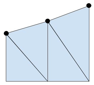
This looks great! But this isn’t the only case we need to consider; when drawing an area we can move the baseline of our area to change the section of the graph that will be shaded. In the previous picture the baseline was always below our data points, but what happens if the baseline is above our data points?
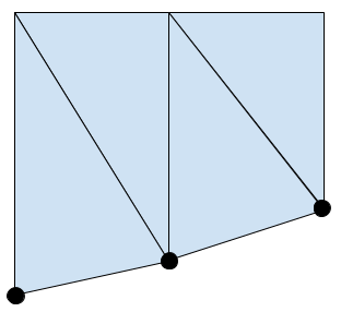
This looks fine, but what if our data points are either side of the baseline?
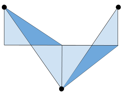
We’ve ended up with some overlap between our triangles. This should never happen, so something has clearly gone wrong…
To handle this we are going to need full control over where each vertex is drawn for each triangle. Unfortunately this means we can’t use GL_TRIANGLE_STRIP, so instead we will use GL_TRIANGLES. The downside to this is that we will have to pass more data to our shader, but we can now control exactly where our triangles are drawn.
The vertex shader
To draw our area we will consider the chart in sections, where each section is the two triangles connecting a pair of data points. We will require six vertices to draw these two triangles, and we will need the data for the current point, the previous point, and the baseline.
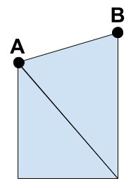
For an example we will consider drawing the area between points A and B, where B is the point we are considering, and A is the previous point. We can pass in the data for the two points, as well as the data for the baseline, through vertex attributes.
Each of our six vertices will have access to the same data, so we need something to control which of the vertices we are currently drawing. To avoid lots of potentially slow conditional logic in our shader we want to aim for something like this (where y0 is the height of the baseline).
gl_Position.x += (aXValue * control) + (aXPrevValue * control);
gl_Position.y += (aYValue * control) + (aYPrevValue * control) + (aY0Value * control) + (aY0PrevValue * control);
We will need some extra logic to handle the case where our data points are either side of the baseline, but we will come back to that later.
The control variable
To correctly draw our triangles we need to know which vertex we are currently drawing. We can determine this by using a control variable that will point us to one of the four corners of the trapezium (remember our two triangles are still forming a trapezium shape). By assigning values to each of our corners we can uniquely identify each one.
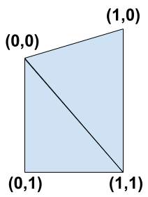
We can see that the two triangles we need to draw are (0,0) -> (0,1) -> (1,1) and (0,0) -> (1,0) -> (1,1). Using a buffer we can pass each vertex we are drawing a vec2 (a 2-component floating point vector) containing one of these pairs of values.
We now have everything we need to determine which vertex we are drawing. Using our vec2 control variable, that we have called aCorner (this may be familiar from when we were drawing lines), we can calculate the correct values for each vertex.
Our X value can be determined by the first value in our vec2 pair, that we access through aCorner.x. If it’s 0 then we should use the previous X value, and if it’s 1 then we should use the current X value.
gl_Position.x += (aXValue * aCorner.x) + (aXPrevValue * (1.0 - aCorner.x));
The Y value isn’t quite as simple as there are four possible values: aYValue, aYPrevValue, aY0Value, and aY0PrevValue. We can determine if we are using the baseline (y0) values based on the second value in our vec2 pair, aCorner.y. Using aCorner.x we can then determine the exact value that we need to use.
gl_Position.y += (1.0 - aCorner.y) * ((aYValue * aCorner.x) + (aYPrevValue * (1.0 - aCorner.x)));
gl_Position.y += aCorner.y * ((aY0Value * aCorner.x) + (aY0PrevValue * (1.0 - aCorner.x)));
This can look confusing but it breaks down to this:
- For (0,0) we use
aYPrevValue - For (1,0) we use
aYValue - For (0,1) we use
aY0PrevValue - For (1,1) we use
aY0Value
That’s everything we need to draw an area where the baseline is above or below our data points! But now we need to consider the case where our data points and baseline cross.
The data point and baseline cross
We will start by reconsidering the situation where our drawing went wrong by looking at an example between points A and B again.
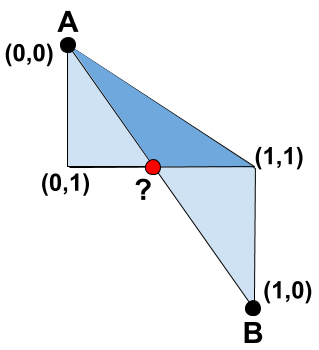
With our corners labelled we can see that the triangles overlap because the corner (1,0) has ended up below the corner (1,1). To fix this we can use the point where the baseline and the line between our data points cross, labelled ?. For our first triangle, instead of drawing (0,0) -> (0,1) -> (1,1) we will draw the triangle (0,0) -> (0,1) -> ?. Similarly the second triangle will become ? -> (1,0) -> (1,1). If we apply this to our example we get something like this.
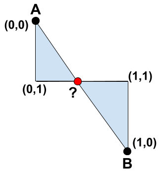
This looks a lot better, so how do we find the point ?? Well the point is on the interception of two straight lines, so if we have the equations of both lines then we can solve for the interception. Time for some Maths!
We start by finding the equation for each line in the form y = mx + c. Our gradient, m, is found using Δy / Δx, the change in the y-axis divided by the change in the x-axis. The constant, c, can then be found by rearranging the formula to c = y - mx and applying the values from one of the points we know.
float yGradient = (aYValue - aYPrevValue) / (aXValue - aXPrevValue);
float yConstant = aYValue - (yGradient * aXValue);

float y0Gradient = (aY0Value - aY0PrevValue) / (aXValue - aXPrevValue);
float y0Constant = aY0Value - (y0Gradient * aXValue);
Once we have equations for both lines, y = mx + c and y = m1x + c1, then we can consider them equal to each other mx + c = m1x + c1, and solve for x, x = (c1 - c) / (m - m1). This gives us the x-coordinate for our interception that we can then apply to one of our line equations, y = mx + c or y = m1x + c1, to get our y-coordinate.
float interceptXValue = (y0Constant - yConstant) / (yGradient - y0Gradient);
float interceptYValue = (yGradient * interceptXValue) + yConstant;
Perfect, we now know the coordinates for the point where the lines cross! However, you may notice that we could have a division by zero here if our gradients are the same. To handle this we will use the step function. We set this up so it will return 1 if our denominator will be zero, and 0 for any other value. If we add this result to our denominator then we can guarantee that it will never be zero. While working in shaders a division by zero will not cause a crash or error, but it will give us an indeterminate value that we cannot use in further calculations.
float denominator = (yGradient - y0Gradient) + step(abs(yGradient - y0Gradient), 0.0);
float interceptXValue = (y0Constant - yConstant) / denominator;
float interceptYValue = (yGradient * interceptXValue) + yConstant;
We’ll see how these results will be used later, and how adding one to our denominator could affect things. But with that sorted we now have our calculations for the interception point finished. So how do we know when to use this point and when we should draw like we were originally?
Using the correct point
To know if we should use the interception point we have to know if our line between the data points and the baseline have crossed. This is actually quite simple to check as we know the Y value for our current and last points, as well as the baseline (y0) values for each point. We can use these values to check if our data points have crossed the baseline with a simple comparison check.
if ((aYValue - aY0Value) * (aYPrevValue - aY0PrevValue) < 0)
We now know the conditions needed to apply our ‘crossing point’ logic, but we need to make sure we are working on the correct vertex. If you recall, the two points we need to change are (1,1) for the first triangle, and (0,0) for the second one. Currently we cannot determine between the points (0,0) and (1,1) for either the first triangle or the second, so we will extend our control variable. By making our control variable, aCorner into a vec3 we gain an extra component to convey the information we need. We will set this third value to either 0, if it’s a vertex we don’t want to move, and 1 if it’s a vertex we do want to move. This can be accessed using aCorner.z, and we can then update our conditional for when to use the interception point.
if (aCorner.z && ((aYValue - aY0Value) * (aYPrevValue - aY0PrevValue) < 0))
Great, but conditionals aren’t the best when it comes to shaders and working on the GPU as they create branches in the code. As we are aiming to get the best performance we will instead use some helper functions to apply our conditional logic, the implementations of these (and other logical functions) can be found in this post on avoiding shader conditionals.
float hasIntercepted = when_lt((aYValue - aY0Value) * (aYPrevValue - aY0PrevValue), 0.0);
float useIntercept = and(aCorner.z, hasIntercepted);
This will give us a value of either 1 or 0, stored in useIntercept, indicating whether our conditional was true or false respectively. We can then use this value as a multiplier to control whether we apply our intercept values or use the corners of the trapezium. Using this method means that we are calculating the intercept values on every invocation of the shader, however the efficiency of these calculations makes this more performant than using a conditional. When using our calculated intercept values we multiply them by useIntercept to control whether they are applied or not.
gl_Position = vec4(interceptXValue * useIntercept, interceptYValue * useIntercept, 0, 1);
Earlier we changed our calculation for a denominator in cases where we were going to divide by zero, this means that our interceptXValue would be incorrect. However this will only occur in situations where there has been no crossing of the lines, and our value for useIntercept is 0. This means that our intercept values are ignored and so we don’t need to worry about the values of them!
Finally we have to update our logic for setting the position based on the corners of our trapezium (when we aren’t using our intercept values). Currently we have this.
gl_Position.x += (aXValue * aCorner.x) + (aXPrevValue * (1.0 - aCorner.x));
gl_Position.y += (1.0 - aCorner.y) * ((aYValue * aCorner.x) + (aYPrevValue * (1.0 - aCorner.x)));
gl_Position.y += aCorner.y * ((aY0Value * aCorner.x) + (aY0PrevValue * (1.0 - aCorner.x)));
We now only want this to be applied when we aren’t using our intercept values, so when the value of useIntercept is 0. To do this we just add an extra multiplier to each update.
gl_Position.x += (1.0 - useIntercept) * (aXValue * aCorner.x) + (aXPrevValue * (1.0 - aCorner.x));
gl_Position.y += (1.0 - useIntercept) * (1.0 - aCorner.y) * ((aYValue * aCorner.x) + (aYPrevValue * (1.0 - aCorner.x)));
gl_Position.y += (1.0 - useIntercept) * aCorner.y * ((aY0Value * aCorner.x) + (aY0PrevValue * (1.0 - aCorner.x)));
And that’s it, we now have a shader that can draw an area chart and handle any value for a baseline! It might seem like there’s a lot going on here but it’s actually not a lot of code, this is the final logic in our shader.
float hasIntercepted = when_lt((aYValue - aY0Value) * (aYPrevValue - aY0PrevValue), 0.0);
float useIntercept = and(aCorner.z, hasIntercepted);

float yGradient = (aYValue - aYPrevValue) / (aXValue - aXPrevValue);
float yConstant = aYValue - (yGradient * aXValue);

float y0Gradient = (aY0Value - aY0PrevValue) / (aXValue - aXPrevValue);
float y0Constant = aY0Value - (y0Gradient * aXValue);

float denominator = (yGradient - y0Gradient) + step(abs(yGradient - y0Gradient), 0.0);
float interceptXValue = (y0Constant - yConstant) / denominator;
float interceptYValue = (yGradient * interceptXValue) + yConstant;

gl_Position = vec4(interceptXValue * useIntercept, interceptYValue * useIntercept, 0, 1);

gl_Position.x += (1.0 - useIntercept) * ((aCorner.x * aXValue) + ((1.0 - aCorner.x) * aXPrevValue));
gl_Position.y += (1.0 - useIntercept) * (1.0 - aCorner.y) * ((aCorner.x * aYValue) + ((1.0 - aCorner.x) * aYPrevValue));
gl_Position.y += (1.0 - useIntercept) * aCorner.y * ((aCorner.x * aY0Value) + ((1.0 - aCorner.x) * aY0PrevValue));
Conclusion
By using GL_TRIANGLES instead of GL_TRIANGLE_STRIP we have gained full control over where we are drawing each triangle, however by doing this we have had to increase the amount of data passed to our shader. This has allowed us to create a shader that can handle varying baseline values, allowing for greater flexibility when creating an area chart.
Ideally we would do a lot of these calculations in a geometry shader, just as we would do this for drawing lines as well. A geometry shader would take the vertices from our vertex shader and transform them, including creating more vertices, before passing them to the fragment shader. Currently this functionality is not available in WebGL, however it is available in OpenGL.
Despite not having a geometry shader we have still leveraged the performance benefits of rendering on the GPU by passing the majority of the work over. We have also made our shader as efficient as possible by avoiding conditional checks, which can slow performance, and instead using operations that are incredibly performant on a GPU.